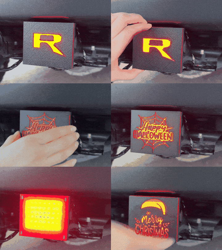
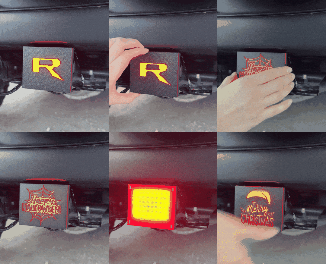
Have you ever looked at your (presumably) empty tow hitch and wondered how you can make it more appealing? Towing something would definitely solve that problem. But what about the 95% of the time you more-than-likely aren't towing? An LED Tow Hitch Cover can help spice up your vehicle's rear end.
12V Electronics
LEDs
CAD
Fabrication
01
Introduction
Have you ever looked at your (presumably) empty tow hitch and wondered how you can make it more appealing? Towing something would definitely solve that problem. But what about 99% of the time you more-than-likely aren't towing? An LED Tow Hitch Cover can help spice up your vehicle's rear end.
02
Project Overview
This project consists of 3 main components:
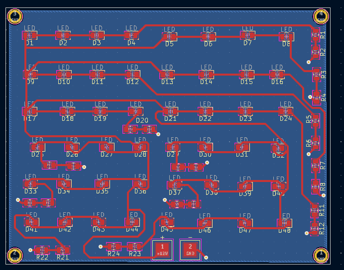
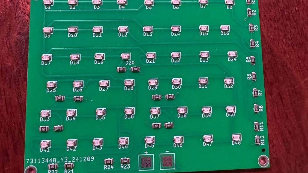
LED PCB: We will need a compact board that can fit within the tow hitch housing
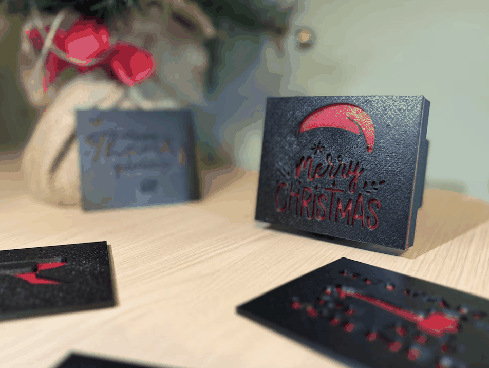
3D Printed, Modular, Enclosure: We will need a durable tow hitch cover enclosure that can protect the PCB and easily swap designs
4-pin Trailer Connector Compatibility: We will need to plug into most vehicle's towing lighting equipment
03
Designing the PCB
Defining Requirements
Before designing the board, it is important to define the requirements. The board must:
Be powered by vehicle's 12V architecture
Comply with local, state, and federal laws
Be bright enough to see both in the day and night
Stay cool within the enclosure (i.e don’t overheat)
Powering with a vehicle's 12V architecture
There are a few sources from which we can pull 12V from a vehicle. I wanted to consider the connection method before even thinking about the overall design because if it is too much of a hassle to plug in, nobody will want to use it! The options I considered were:
Wiring from the 12V battery to the rear (requires harnessing)
Tapping a taillight harness (requires a splitter)
Powering it externally (requires additional circuitry and battery)
Plugging into trailer 4-pin plug (requires 4-pin connector).
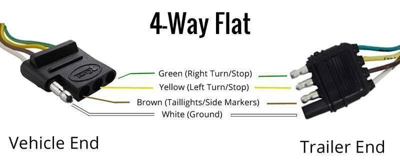
Many of these options required additional work or additional components. However, the trailer 4-pin plug stood out as a great potential solution. Many vehicles optioned with a tow-hitch get a trailer plug/harness included. This means a 4-pin male connector connected to the female receptical can give us easy 12V access. In addition to that, these cost anywhere from $1-$3 on Amazon, making it a cost-effective way to power the board. A typical 4-pin trailer connector diagram looks something like this:
For the first version of this project, we can ignore the green and yellow wires because we will only want the LEDs on when the vehicle's DRLs are on. This means we will only need two power pads on our board. One for the white wire (GND) and one for the brown wire (DRLs/12V).
LEDs and Brightness(V1)
Because this will be acting as an additional light on the back of the vehicle, the only legal way to have it continuously be on is if we treat it as a brake light. This means we will be limited to red LEDs.
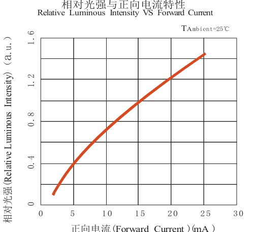
The red led constraint allows us to calculate the intensity and current the LEDs will be running at. Ultimately, the brightness of the LED will be determined by how you drive it. In other words, how much current will flow through them? For the red LED I found, the forward current (If) is 25 mA. According to the manufacturer's chart, driving the LED at this current will give us the highest relative luminous intensity. (This assumes an ambient temperature of 25 degrees, which is a mistake that will bite use later on).
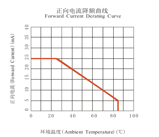
The current curve is not the only graph worth paying attention to. The ‘Forward Current Derating Curve’ is a graph that essentially tells you what current you will want to drive your LEDs, given a specific temperature, to avoid overheating your LEDs. At 25 mA, we are assuming that our LEDs will be operating at about 25 °C ambient temperature. However, we know this board will be in a fully sealed enclosure (which means no airflow) and will be sitting outside.
This is tricky. Vehicles, especially while driving and getting beat under the sun, can get extremely hot. We can always choose more robust LEDs but they can get costly. In addition, relative luminous intensity, as a human, means nothing to me. How do I know if the highest intensity is ‘bright enough’? What if it is too bright? Ultimately, I decided the best approach for me will be to drive them at their brightest, 25mA. Afterwards, we can do real-world testing at different conditions to see how our LEDs fair. From there, we can determine the optimal driving current for our needs.
Current Calculations
There is one more thing we will have to handle before moving onto our schematic. How many LEDs can we drive? LEDs have something called a forward voltage (Vf). This is the amount of voltage needed to get current to flow across an LED. It differs between LEDs and colors, but for red, we can say it is a Vf of 2 volts (according to the manufacturer). This means if we have 12V from our vehicle, we can put 6 LEDs in series, because each LED 'consumes' 2V from our total 12V.
Six LEDs alone, however, will not produce enough light for our entire tow hitch cover. So, we can do something neat; we can add another series of 6 LEDs in PARALLEL with our initial 6. This goes back to our basic electronic fundamentals. In parallel, each branch receives the same voltage from the power supply. This means that we can add as many series of 6 LEDs, in parallel, until we reach the total light output we want (assuming your power supply can output the required current).
Given what we learned about LED in series and parallel, we still have one more open item. Remember when I said you could use 6 LEDs? That is not entirely true. The forward voltage (Vf) of the LED for a variety of reasons including manufacturing defects and changes inambient temperature. So, to compensate for that variability, we use 4 or 5 LEDs instead of 6. Due to our very wide operating temperature, I will opt to use 4 LEDs in series.
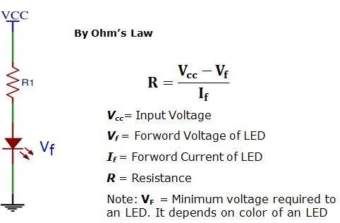
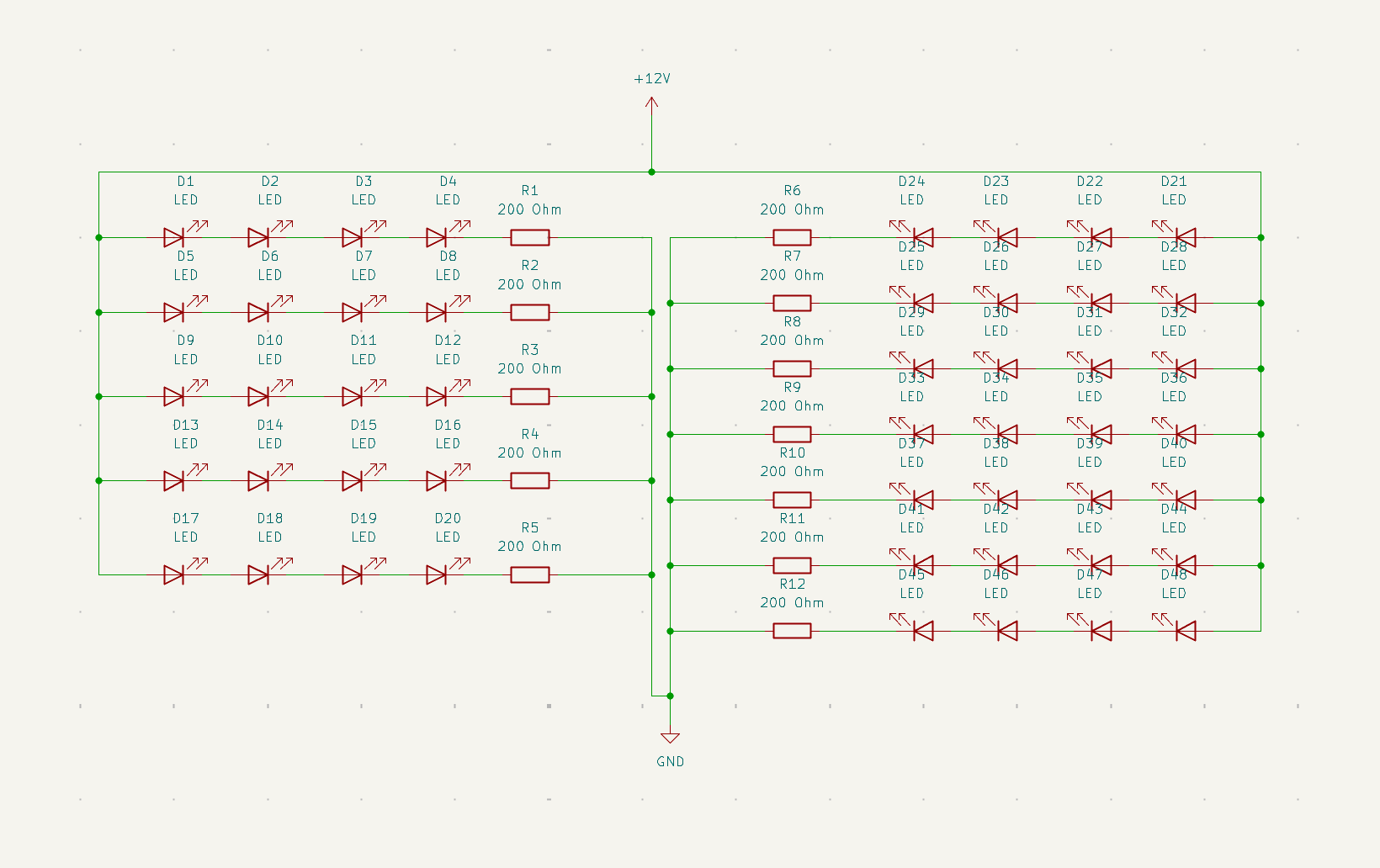
With 4 LEDs in series, the final piece of the puzzle becomes a bit more clear. How do we safely dissipate the remaining voltage from our supply? How do we set the operating current for those 4 LEDs? We use a current-limiting resistor. We can calculate the current-limiting resistor using this equation, based on our requirements: (12V - 8V)/25mA = 160 Ohms. This means at the end of each of our 4 series LEDs we will need a 160 ohm resistor. This resistor will, at a minimum, have to be able to safely dissipate 0.1 W of power, or 100 mW.
I want to re-iterate that we are driving our LEDs a little hard at 25 mA, but with real-world testing we can find the range we actually want to run at.
Schematic
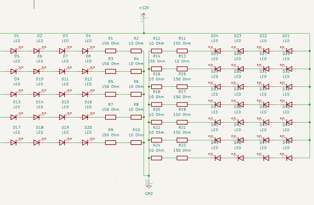
With everything in place, we can create our fairly simple looking schematic. Looking at it, you may be asking - “Why did you use a 150 Ohm and 10 Ohm in series?” This is not ideal, but the simple reason is cost. JLCPCB, sadly, does not offer 160 Ohm resistors at their 'basic' tier, meaning that if we use them, it will quickly drive up the price. So, using 150 and 10 was a reasonable compromise without any destructive drawbacks.
Staying cool within the enclosure
The final part of our PCB is making sure it keeps cool. Driving the LEDs at a smaller current is a reasonable way to do this, but we haven't done a real-world brightness test. So, we can try some things in our PCB, such as:
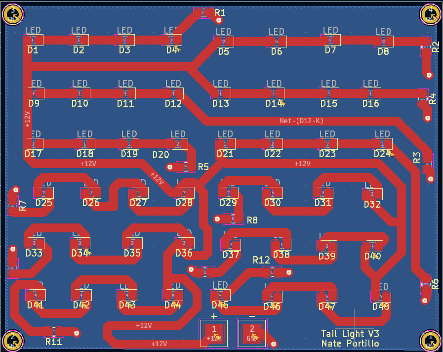
Make a big copper pour for our GND plane. This can act as a thermal spreader and give our current a quick and direct path back to GND.
Make wider power traces. Wider traces have lower electrical resistance, which means less power is lost as heat due to resistive losses. A useful equation is R = (p * L)/A (Admittedly, V1 could have made those traces MUCH thicker).
Make mounting holes that can act for thermal relief if needed.
04
The PCB!
The board was sent to the manufacturer, JLCPCB. This board was fairly cheap so it was manufactured and assembled both the manufacturer.
05
Designing the Enclosure
The design of the enclosure, was first and foremost, dictated by the size of a tow-hitch. It would have to be able to securely sit inside, and only slightly protrude paste the 2 by 2 opening. A few other requirements I wanted to meet were:
Use a material robust enough to avoid sun fading and sustain high heat.
Use the PCB mounting holes to air gap the board to avoid melted plastic (a second time).
Use magnets to allow for modular and hot-swappable designs.
Use a cap design that will be water proof, dust proof, etc.
Given these requirements, I used fusion 360 to design a 2-part enclosure.
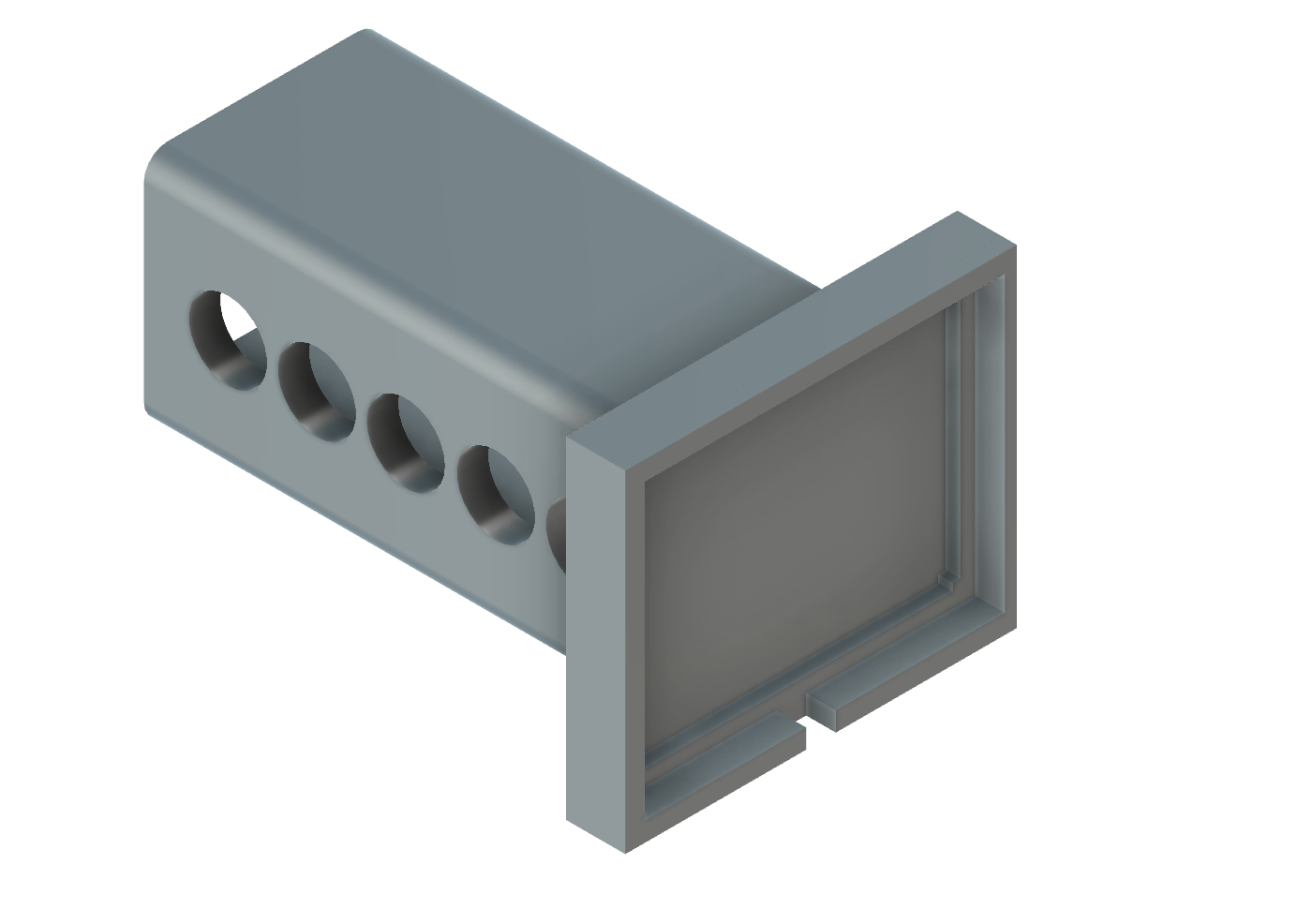
First is the base. This was designed as a solid piece so no water ingress can take place. The PCB will sit with only the edges (i.e where this is the least heat) touch the plastic. The material will be Carbon Fiber PETG for extra durability.
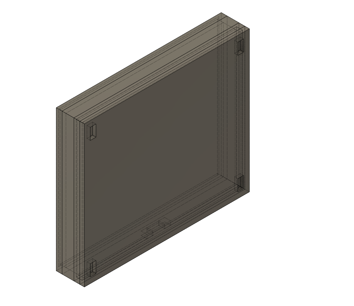
Second is the cap. This will be translucent PETG to allow for the LED light to shine through. The only entry point is below, for wires. This way the seal can be facing away from any downward forces, making a water entry more difficult. It has 4 slots for pressure-fit magnets. This will allow the design swapping component.
Finally is the cap. This is a mix of dark, non-transparent material(PETG-CF) and a thin, shallow, translucent layer. It also has 4 pressure-fit magnet slots to attach to the main tow-hitch cover.
06
Testing
With the enclosure design ready and the PCBs available; do you I said we would have to do some testing? What exactly does that entail? We received 5 boards from JLCPCB. I printed a few enclosures and ran them indoors (using a power supply), and outdoor in the heat.
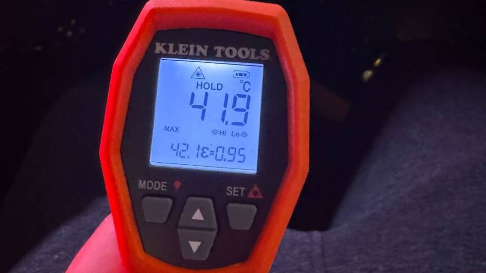
Sadly, I didn't capture many pictures of this process, but what I can tell you from real-world testing is that 25 mA in a full enclosure resulted in melted plastic and really hot PCBs/LEDs. As you can see, in some of the indoor tests, at 25mA, the LEDs were getting to 40 degrees Celsius. This is in a cooled environment!
Given the results, I added an additional current-limiting resistor, in-line with the trailer pin connector wiring. This limited the entire boards brightness, and let me get a feel for the ‘sweet spot’ I want in brightness and heat dissipated by the board.
07
Future Improvements
The 3D printed design is very solid, but there are a few improvements that can be made on the PCB side:
Wider power traces.
Better component placement. Some spots on the board are very cool and some portions have hotspots.
Larger current-limiting resistor value. Currently, some resistors are wired in-line with the 4-pin harness to lower the 25 mA forward current. This isn't ideal, and we can easily change our current limiting resistor equation to 15-20 mA after our real-world testing. This means increasing our 160-ohm resistance to anywhere from 200-260 ohms.
Ambient Derating! This still isn't exactly where I would like it to be, especially for an automotive application in California. We get up to 110F days in the summer. However, I want to note that because our 4-pin connector only relies on DRLs (auto DRLs are usually not on during the day), chances are the board will be on mostly at night (meaning it is cooler).
08
Conclusion
After all is said and done, we get a cool, robust, tow hook cover that lights up!
09
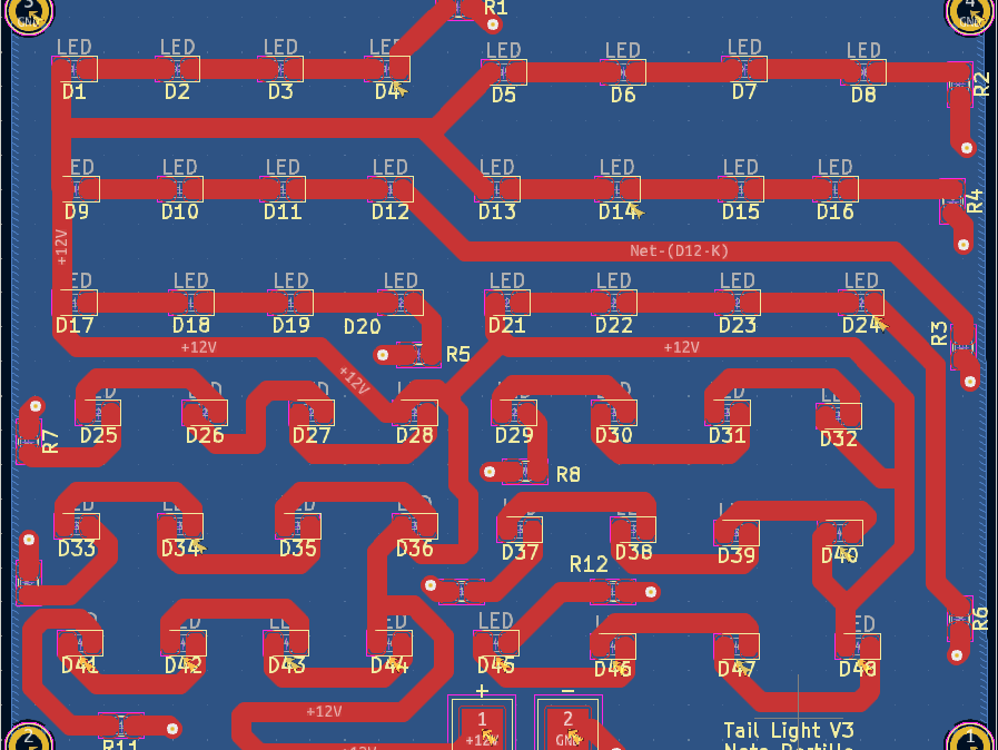
V3 Has Been Created
Features:
Lower current driving the LEDs
Consolidated & larger (value, not package) resistors. Down from 24 resistors to 12.
Wider traces! Better utilization and heat distribution throughout the board.
UPDATE: I’m happy to say it has been almost two years using the V3 version in California and I have not seen any issues other than the magnets rusting (they are exposed directly to the elements). I think this may warrant a V2 for the enclosure, with thin layers that also cover the magnets.