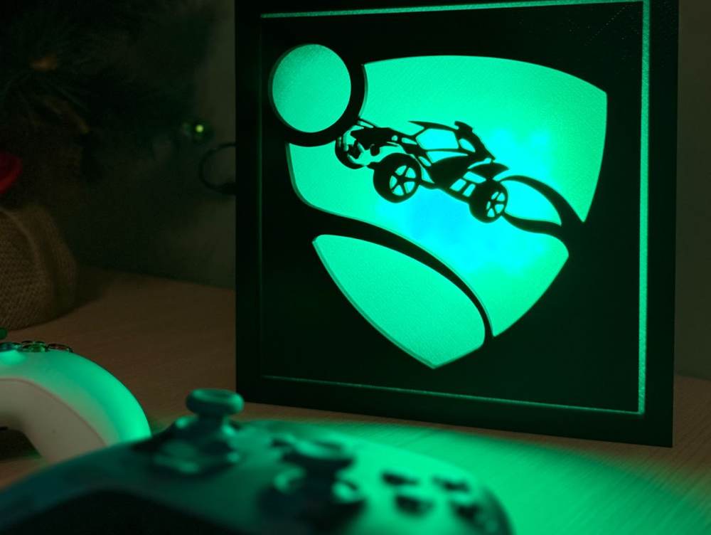
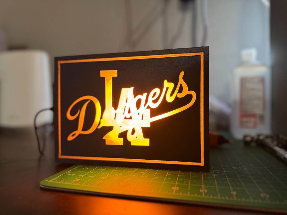
Can a lamp be fashionable? An interior designer would say so. This lamp definitely isn't. The cool thing is that it can be. I'm going to be introducing what I consider a pretty neat product. Similar to my previous project, the LED Tow Hitch, this lamp takes advantage of magnets to allow a user to swap designs based on their personality, mood, season, etc. Even better, because this is a lamp meant to accessorize your desk or a shelf, we are able to integrate powerful RGB LEDs and a microcontroller, allowing for some pretty fun effects.
Firmware
Electronics
3D Printing
Prototyping
01
Introduction
Can a lamp be fashionable? An interior designer would say so. This lamp definitely isn't. The cool thing is that it can be. I'm going to be introducing what I consider a pretty neat product. Similar to my previous project, the LED Tow Hitch, this lamp takes advantage of magnets to allow a user to swap designs based on their personality, mood, season, etc. Even better, because this is a lamp meant to accessorize your desk or a shelf, we are able to integrate powerful RGB LEDs and a microcontroller, allowing for some pretty fun effects.
02
Project Overview
This project consists of 3 main components:
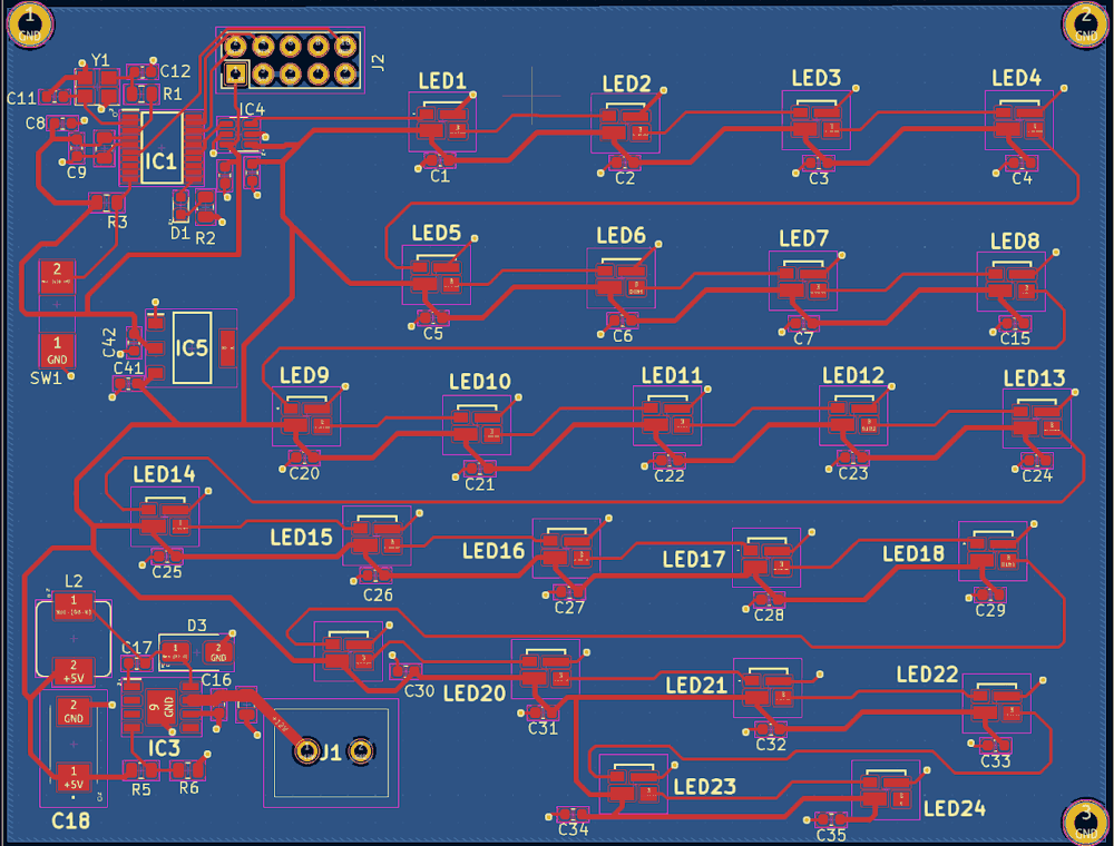
LED PCB: We will need to create a compact board that can fit within the lamp housing
Firmware We will need to create firmware that will run on the microcontroller for the LED effects
3D Printed, Modular, Enclosure: We will need a stylish enclosure that can protect the PCB and easily swap designs
03
Power
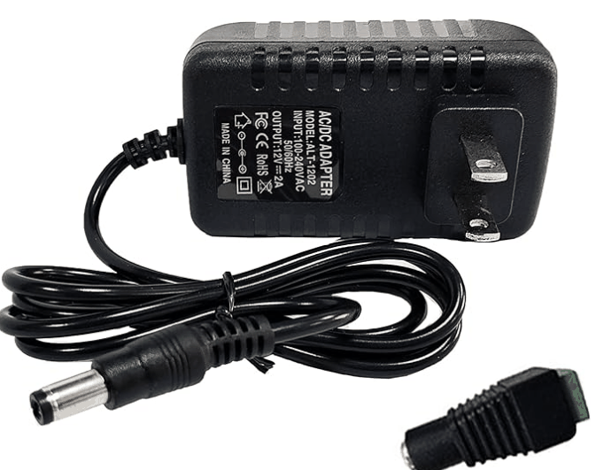
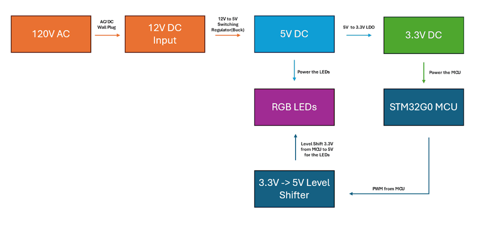
Before starting a design, I like to imagine how I want the product to be powered. A battery? USB? In this lamp's case, I imagined myself wanting to plug it into an outlet near my desk. With this in mind, I have had great experiences using AC/DC wall plugs. They are cheap, plentiful on Amazon, and they are sold in a wide variety of voltages; more importantly, amp ratings.
In addition to how it will be powered, what voltage it will be powered at is just as important. When first starting this project, I envisioned myself taking the MCU/power electronics across projects, so I went with a 12V input that will allow me to power higher voltage components if needed and step down anything else for the lower voltage electronics.
04
RGB Leds
RGB LEDs are everywhere and very easy to find. However, I was looking at JLCPCB to do the assembly of this board for me. This, once again, meant I was a bit limited in the components I could pick. Even more so for the LEDs because JLCPCB decided to designate many of these as 'Extended Parts' ($) AND as 'Standard' parts ($$$).
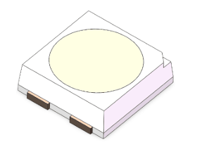
To narrow down my choices, I knew I wanted an RGB LED with a built-in IC. This means I won't have to worry about managing current like I had to with the tow hitch cover. I also didn't need any high-current LEDs, as those tend to be more work, especially if they require a heat sink. This narrowed down my choices significantly, and I settled on the SK6812 series LED.
05
Microcontroller
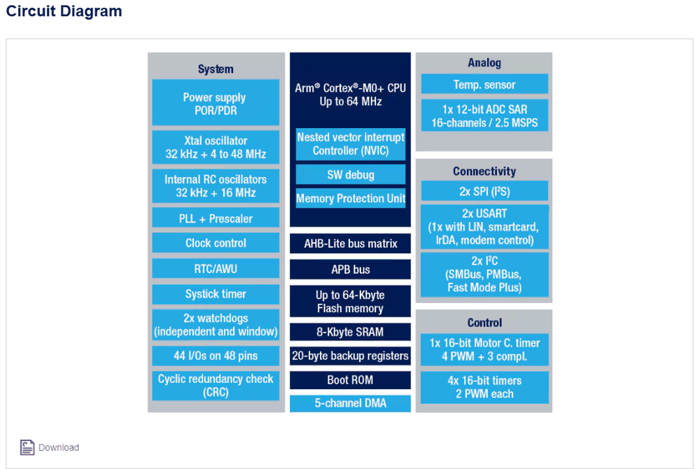
For the microcontroller, I knew I was going to go with an MCU from ST's lineup. This is mainly because I am very familiar with their microcontrollers and tools. Since the SK6812 LEDs require PWM it was clear I would, at a minimum, need the MCU to have some on-board timers. I settled on ST's STM32G0F6. This is considered ST's 'Budget Line'. The G0 has basic peripherals like I2C, SPI, UART, and a speedy enough 64Mhz clock. This was more than enough for my application and future applications. In hindsite, the F6 in particular (once taking into account an external clock, SWD Wire, Reset Wire, etc.) runs out of pins really quick. It makes a great application-specific MCU, but if you are looking for upgradability, I would get a higher pin package. Additionally, the low RAM and Flash size (32K/8K) will have you making sure every variable and line of code in your firmware needs to be there.
06
System Design
Given these components, we can map a high-level overview of our system:
07
Pin Selection
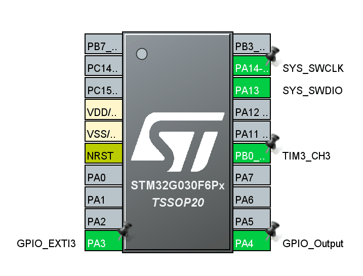
We set our SWDIO, SWCLK, and Timer (PWM) pins. We also add an additional pin, configured for an interrupt, so that we can use a button to change effects. Lastly, we have an output pin to drive an LED and make sure power/functionality is there.
08
The Schematic
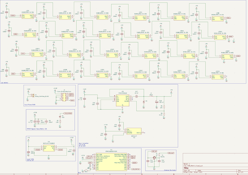
Some key points of the schematic:
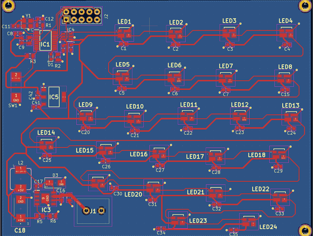
Following the LED's datasheet, each individual LED needs a decoupling capacitor. This requirement is iffy, but caps are so cheap, it was not a difficult addition.
We include the design for an external clock, but it doesn't make the end design. The pads are nice to have if we need a more accurate oscillator in the future.
Header pins are included for ST-Link (Firmware Flashing). So, we need to expose those pins for SWDIO, SWCLK, RESET, etc.
We use a switching regulator and then an LDO. The switching regulator (Buck) is better for stepping down those larger voltage differences while dealing with larger currents (3A). Once converted to 5V, a simple LDO can save us space, complexity, and cost. These are much cheaper than a buck and should be able to easily handle the current/power requirements of the STM32G0.
Don't forget, we need the level shifter! The LED's minimum logic voltage is (0.7 * Vdd). This means the minimum is technically 3.5V. However, many reports on the sister product line of SK LEDs mention that some don't play nice with lower than 4V. So, we level shift our MCU's 3.3V to 5V so that we don't face any problems later on.
We also leave exposed pads to have flexability with the button that will change LED effects.
09
The PCB
10
LED Driving (PWM)
The SK6812 line of LEDs requires PWM at the logic input in order to be able to program colors and effects. According to the datasheet, the minimum symbol period is 1.2 uS. If we convert this to frequency (1/T), we get approximately 833 kHz. Given this, we can calculate our counter period for our timer. Our clock is running at 16 MHz, so we can divide this by 833 MHz and get approx. 19-1 for our ARR. If we wanted an application-specific PWM duty cycle, we could set the CCR. For example, a CCR of 9 would give us a 50% d.c. (ARR/CCR). For the SK6812, we need a bit 0 for.30 (6/18) and bit 1 for approximately.67 (12/18).
11
DMA
I would like to say I created the LED effects myself, but the truth is, LED effects can be very tedious to make once you get beyond basic red, blue, and green. So, I adapted code from this article as the basis for my effects creation. If you want to read more about how to set up DMA (Direct Access Memory) for your timer to get the throughput necessary for these intensive effects, feel free to read this guide directly! https://www.thevfdcollective.com/blog/stm32-and-sk6812-rgbw-led
Remember I said we needed to switch through the effects somehow? That is where our button comes in. To initially set it up, you have to make sure you configure your pin to trigger on external interrupts. Once that is configured, you can write your code within a GPIO callback.
Normally, you want to keep your interrupts as short as possible. The shorter, the better. You are interrupting your code in order to handle this request! However, with buttons, especially ones that will be soldered by hand, you can get a lot of mechanical noise. There are hardware solutions you can implement using capacitors, but I opted for a software solution. When we press a button, we may get a click and a ton of quick little oscillations after the fact. So, by ignoring those small oscillations, we can get a solid click. In this code, we essentially 'timestamp' our current time and the time the button was last pressed. If that time is less than 500 ms, we ignore it. If it is greater, we can assume it was a solid press (and not noise) and continue to change effects. This 500-ms time was chosen based on trial and error and could change depending on the button.
Within this code we also handle a sleep variable, used to put our MCU into a lower power state, and we also control our color switching case statement within the main loop. Again, we do this with simple variables because we want to keep our interrupt as short as possible! Lastly, in the main loop, we handle our effects with a case statement and include our low power modes.
12
Future Improvements
The 3D printed design is very solid (adapted from our LED Tow Hitch), but there are a few improvements that can be made on the PCB side:
Clean up the firmware! Currently, these LED effects can use up my very limited Flash memory, so I'd like to make optimizations in the future to make it more lean
Focus more on modular design. The intent with this board was to make an LED lamp AND to allow my PCB to be flexible enough to use on other projects. I'd like to continue working on supporting more voltages, currents, etc.
13
Conclusion
After all is said and done, we get a cool, sleek, RGB lamp with swappable covers!